circuitschematicdiagram.blogspot.com circuitschematicdiagram.blogspot.com

circuitschematicdiagram.blogspot.com

CIRCUIT DIAGRAM | SKEMA RANGKAIAN | ELEKTRONIKA

SKEMA | RANGKAIAN | SKEMA RANGKAIAN | SEKEMA | ELEKTRO | ELEKTRONIKA | ELECTRONIC | GADGED | MACHINE | SCHEMATIC DIAGRAM | GRAPHIC CIRCUIT | GRAFIK | DESIGN | ALARM | AUDIO | AMPLIFIER | SPEAKER | CONTROL | COMPUTER | LAPTOP | HANDPHONE | RADIO | TELEVISION | MOTOR | ROBOT | LED | LIGHT | MICROCONTROLLER

http://circuitschematicdiagram.blogspot.com/

WEBSITE DETAILS
SEO
PAGES
SIMILAR SITES

TRAFFIC RANK FOR CIRCUITSCHEMATICDIAGRAM.BLOGSPOT.COM

TODAY'S RATING

>1,000,000

TRAFFIC RANK - AVERAGE PER MONTH

BEST MONTH

November

AVERAGE PER DAY Of THE WEEK

HIGHEST TRAFFIC ON

Saturday

TRAFFIC BY CITY

CUSTOMER REVIEWS

Average Rating: 4.8 out of 5 with 11 reviews
5 star
9
4 star
2
3 star
0
2 star
0
1 star
0

Hey there! Start your review of circuitschematicdiagram.blogspot.com

AVERAGE USER RATING

Write a Review

WEBSITE PREVIEW

Desktop Preview Tablet Preview Mobile Preview

LOAD TIME

2.2 seconds

FAVICON PREVIEW

  • circuitschematicdiagram.blogspot.com

    16x16

  • circuitschematicdiagram.blogspot.com

    32x32

CONTACTS AT CIRCUITSCHEMATICDIAGRAM.BLOGSPOT.COM

Login

TO VIEW CONTACTS

Remove Contacts

FOR PRIVACY ISSUES

CONTENT

SCORE

6.2

PAGE TITLE
CIRCUIT DIAGRAM | SKEMA RANGKAIAN | ELEKTRONIKA | circuitschematicdiagram.blogspot.com Reviews
<META>
DESCRIPTION
SKEMA | RANGKAIAN | SKEMA RANGKAIAN | SEKEMA | ELEKTRO | ELEKTRONIKA | ELECTRONIC | GADGED | MACHINE | SCHEMATIC DIAGRAM | GRAPHIC CIRCUIT | GRAFIK | DESIGN | ALARM | AUDIO | AMPLIFIER | SPEAKER | CONTROL | COMPUTER | LAPTOP | HANDPHONE | RADIO | TELEVISION | MOTOR | ROBOT | LED | LIGHT | MICROCONTROLLER
<META>
KEYWORDS
1 postingan lama
2 beranda
3 langganan postingan atom
4 other circuit
5 label
6 alarm
7 amplifier
8 audio
9 battery
10 charger
CONTENT
Page content here
KEYWORDS ON
PAGE
postingan lama,beranda,langganan postingan atom,other circuit,label,alarm,amplifier,audio,battery,charger,crossover,detector,equalizers,flashing,generator,hifi,inverter,loudspeaker,microphone,mosfet,power,power amplifier,power supply,radio,remocer,speaker
SERVER
GSE
CONTENT-TYPE
utf-8
GOOGLE PREVIEW

CIRCUIT DIAGRAM | SKEMA RANGKAIAN | ELEKTRONIKA | circuitschematicdiagram.blogspot.com Reviews

https://circuitschematicdiagram.blogspot.com

SKEMA | RANGKAIAN | SKEMA RANGKAIAN | SEKEMA | ELEKTRO | ELEKTRONIKA | ELECTRONIC | GADGED | MACHINE | SCHEMATIC DIAGRAM | GRAPHIC CIRCUIT | GRAFIK | DESIGN | ALARM | AUDIO | AMPLIFIER | SPEAKER | CONTROL | COMPUTER | LAPTOP | HANDPHONE | RADIO | TELEVISION | MOTOR | ROBOT | LED | LIGHT | MICROCONTROLLER

INTERNAL PAGES

circuitschematicdiagram.blogspot.com circuitschematicdiagram.blogspot.com
1

CIRCUIT DIAGRAM | SKEMA RANGKAIAN | ELEKTRONIKA: SIMPLE BENCH AMPLIFIER SCHEMATIC DIAGRAM

http://circuitschematicdiagram.blogspot.com/2011/09/simple-bench-amplifier-schematic.html

SIMPLE BENCH AMPLIFIER SCHEMATIC DIAGRAM. SIMPLE BENCH AMPLIFIER SCHEMATIC DIAGRAM. The gain of the LM386 can be controlled by the capacitor across pins 1 and 8. With the 10u cap shown above, voltage gain is 200, omitting this capacitor and the gain of the amplifier is 20. CIRCUIT NICD - NIMH BATTERY CHARGER SCHEMATIC DIAGRAM. NiCd – NiMH Battery Charger circuit diagram Note: I is 1/10 of the battery’s charging capacity. For example if battery has a rated cap. SKEMA RANGKAIAN CIRCUIT SCHEMATIC DIAGRAM.

2

CIRCUIT DIAGRAM | SKEMA RANGKAIAN | ELEKTRONIKA: SKEMA RANGKAIAN CIRCUIT SCHEMATIC DIAGRAM

http://circuitschematicdiagram.blogspot.com/2011/07/skema-rangkaian-circuit-schematic.html

SKEMA RANGKAIAN CIRCUIT SCHEMATIC DIAGRAM. Trainer Mikro Lengkap berbasis SMARTAVR ATmega 8535 ver 4.0. SMARTAVR ATmega 8535 ver 2.0. Kit mikrokontroler berbasis ATMega8535, kabel avr programmer parallel port, led dan saklar, regulator built in, lcd 2x16 M1632, LM 35DZ, kabel, cd program, contoh program dan tutorial, 2 bh Sevent segment dan trainsistor, software AVR C Compiler dan Bascom AVR, sangat tepat sebagai trainer board untuk belajar AVR otodidak, karena sudah ada adc 8 channel 10 bit. Kit mikroko...

3

CIRCUIT DIAGRAM | SKEMA RANGKAIAN | ELEKTRONIKA: CIRCUIT POWER AMPLIFIER 2000 WATT SCHEMATIC DIAGRAM

http://circuitschematicdiagram.blogspot.com/2011/08/circuit-power-amplifier-2000-watt.html

CIRCUIT POWER AMPLIFIER 2000 WATT SCHEMATIC DIAGRAM. CIRCUIT POWER AMPLIFIER 2000 WATT SCHEMATIC DIAGRAM. This is linear amplifier which need advance knowledge in electronics since the schematic diagram is very complex for hand made circuit. CIRCUIT NICD - NIMH BATTERY CHARGER SCHEMATIC DIAGRAM. NiCd – NiMH Battery Charger circuit diagram Note: I is 1/10 of the battery’s charging capacity. For example if battery has a rated cap. CIRCUIT POWER AMPLIFIER 2000 WATT SCHEMATIC DIAGRAM.

4

CIRCUIT DIAGRAM | SKEMA RANGKAIAN | ELEKTRONIKA: CIRCUIT NICD - NIMH BATTERY CHARGER SCHEMATIC DIAGRAM

http://circuitschematicdiagram.blogspot.com/2011/08/circuit-nicd-nimh-battery-charger.html

CIRCUIT NICD - NIMH BATTERY CHARGER SCHEMATIC DIAGRAM. NiCd – NiMH Battery Charger circuit diagram. I is 1/10 of the battery’s charging capacity. For example if battery has a rated capacity of 1700mA then? The input voltage must be at least 3 times the battery’s voltage. For example an input voltage of 25V can charge a 8,4V (9V) battery. CIRCUIT NICD - NIMH BATTERY CHARGER SCHEMATIC DIAGRAM. CIRCUIT POWER AMPLIFIER 2000 WATT SCHEMATIC DIAGRAM. SKEMA RANGKAIAN CIRCUIT SCHEMATIC DIAGRAM.

5

CIRCUIT DIAGRAM | SKEMA RANGKAIAN | ELEKTRONIKA: CIRCUIT 13.8 VOLT 20 A TRANSFORMERLESS POWER SUPPLY SCHEMATIC DIAGRAM

http://circuitschematicdiagram.blogspot.com/2011/08/circuit-138-volt-20-transformerless.html

CIRCUIT 13.8 VOLT 20 A TRANSFORMERLESS POWER SUPPLY SCHEMATIC DIAGRAM. CIRCUIT 13.8 VOLT 20 A TRANSFORMERLESS POWER SUPPLY SCHEMATIC DIAGRAM. This 13.8 Volt 20 A regulated transformerless power supply. 20A transformer is very-very expensive, large in size and very heavy in weight. CIRCUIT NICD - NIMH BATTERY CHARGER SCHEMATIC DIAGRAM. NiCd – NiMH Battery Charger circuit diagram Note: I is 1/10 of the battery’s charging capacity. For example if battery has a rated cap.

UPGRADE TO PREMIUM TO VIEW 0 MORE

TOTAL PAGES IN THIS WEBSITE

5

LINKS TO THIS WEBSITE

schematicwiring.blogspot.com schematicwiring.blogspot.com

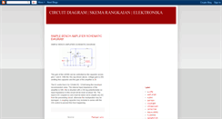
ELECTRONIC SCHEMATIC DIAGRAM | WIRING DIAGRAM | CIRCUIT DIAGRAM RESOURCES: POWER AMPLIFIER DARLINGTON 600 WATT CIRCUIT

http://schematicwiring.blogspot.com/2011/06/power-amplifier-darlington-600-watt.html

POWER AMPLIFIER DARLINGTON 600 WATT CIRCUIT. This Power amplifier circuit produces output power up to 300 watts ( 8ohms) pada masing-masing channelnya. It is a high fidelity audio power amplifier. Designed for demanding consumer and pro-audio applications. You can also use this circuit with AV receivers, Audiophile power amps, Pro Audio High voltage industrial applications etc. 500WATT POWER AMPLIFIER CIRCUIT SCHEMATIC DIAGRAM. POWER AMPLIFIER DARLINGTON 600 WATT CIRCUIT. Template Simple. Diberdayaka...

schematicwiring.blogspot.com schematicwiring.blogspot.com

ELECTRONIC SCHEMATIC DIAGRAM | WIRING DIAGRAM | CIRCUIT DIAGRAM RESOURCES: 500WATT POWER AMPLIFIER CIRCUIT SCHEMATIC DIAGRAM

http://schematicwiring.blogspot.com/2011/07/500watt-power-amplifier-circuit.html

500WATT POWER AMPLIFIER CIRCUIT SCHEMATIC DIAGRAM. There are some important updates to this project, as shown below. Recent testing has shown that with the new ON Semi transistors it is possible to obtain a lot more power than previously. The original design was very conservative, and was initially intended to use 2SA1492 and 2SC3856 transistors (rated at 130W) - with 200W (or 230W) devices, some of the original comments and warnings have been amended to suit. And can kill you. This Power amplifier circu...

schematicwiring.blogspot.com schematicwiring.blogspot.com

ELECTRONIC SCHEMATIC DIAGRAM | WIRING DIAGRAM | CIRCUIT DIAGRAM RESOURCES: STK 4192 POWER AMPLIFIER 50 WATT STEREO CIRCUIT SCHEMATIC DIAGRAM

http://schematicwiring.blogspot.com/2011/07/stk-4192-power-amplifier-50-watt-stereo.html

STK 4192 POWER AMPLIFIER 50 WATT STEREO CIRCUIT SCHEMATIC DIAGRAM. STK 4192 POWER AMPLIFIER 50 WATT STEREO CIRCUIT SCHEMATIC DIAGRAM. The STK4102II series (STK4192II) and STK4101V series (high-grade type) are pin-compatible in the output. Range of 6W to 50W and enable easy design. Small-sized package whose pin assignment is the same. As that of the STK4101II series. Built-in muting circuit to cut off various kinds of pop noise. Greatly reduced heat sink due to substrate temperature 125°C guaranteed.

schematicwiring.blogspot.com schematicwiring.blogspot.com

ELECTRONIC SCHEMATIC DIAGRAM | WIRING DIAGRAM | CIRCUIT DIAGRAM RESOURCES: DIGITAL SPEEDOMETER CIRCUIT SCHEMATIC DIAGRAM

http://schematicwiring.blogspot.com/2011/07/digital-speedometer-circuit-schematic.html

DIGITAL SPEEDOMETER CIRCUIT SCHEMATIC DIAGRAM. DIGITAL SPEEDOMETER CIRCUIT SCHEMATIC DIAGRAM. This circuit serves to show the speed of the vehicle in kmph. An opaque disc is mounted on the spindle attached to the front wheel of the vehicle. The disc has about equidistant holes on its periphery. On one side of the disc an infrared LED is fixed and on the opposite. 500WATT POWER AMPLIFIER CIRCUIT SCHEMATIC DIAGRAM. POWER AMPLIFIER DARLINGTON 600 WATT CIRCUIT. DIGITAL SPEEDOMETER CIRCUIT SCHEMATIC DIAGRAM.

schematicwiring.blogspot.com schematicwiring.blogspot.com

ELECTRONIC SCHEMATIC DIAGRAM | WIRING DIAGRAM | CIRCUIT DIAGRAM RESOURCES: SIMPLE SWITCH TIME DELAY CIRCUIT DIAGRAM

http://schematicwiring.blogspot.com/2011/10/simple-switch-time-delay-circuit.html

SIMPLE SWITCH TIME DELAY CIRCUIT DIAGRAM. SIMPLE SWITCH TIME DELAY CIRCUIT DIAGRAM. 500WATT POWER AMPLIFIER CIRCUIT SCHEMATIC DIAGRAM. 500Watt Power Amplifier There are some important updates to this project, as shown below. Recent testing has shown that with the new ON Se. POWER AMPLIFIER DARLINGTON 600 WATT CIRCUIT. This Power amplifier circuit produces output power up to 300 watts ( 8ohms) pada masing-masing channelnya. It is a high fidelity audio power. DIGITAL SPEEDOMETER CIRCUIT SCHEMATIC DIAGRAM.

UPGRADE TO PREMIUM TO VIEW 1 MORE

TOTAL LINKS TO THIS WEBSITE

6

OTHER SITES

circuitscenerecords.bandcamp.com circuitscenerecords.bandcamp.com

Music | circuitscenerecords

Old Friends, New Bruises. We Made It (F* K Yeah! We Are The Sleepless. Hell Money / Meanwhile, In Hell. This Is Not A Record, This Is All The Best Tapes. All The Best Tapes. We are a DIY label and distro based in South Wales, UK. The label is run by a collective of like minded musicians who have been around the UK punk and hardcore scene for the best part of 10 years . Everything we make (which isnt a lot) gets reinvested into the bands so they can continue to record and play gigs. Switch to mobile view.

circuitschematic.blogspot.com circuitschematic.blogspot.com

Electronic Circuit Schematic Wiring Diagram

Electronic Circuit Schematic Wiring Diagram. TDA1562Q Audio Power Amplifier 36 Watt. The TDA1562Q Audio Power Amplifier 36 Watt. TDA1562Q Audio Power Amplifier 36 Watt. As can be seen from the photos and the circuit diagram, the Mighty Midget uses just a handful of parts. It's built on a PC board that measures just 104mm x 39mm but while its size may be modest, these's nothing at all modest about its power output. And the noise and distortion figures are pretty good too. Output power:36W RMS into 4R.

circuitschematic.net circuitschematic.net

circuitschematic.net - Registered at Namecheap.com

This domain is registered at Namecheap. This domain was recently registered at Namecheap. Please check back later! This domain is registered at Namecheap. This domain was recently registered at Namecheap. Please check back later! The Sponsored Listings displayed above are served automatically by a third party. Neither Parkingcrew nor the domain owner maintain any relationship with the advertisers.

circuitschematicdiagram.blogspot.com circuitschematicdiagram.blogspot.com

CIRCUIT DIAGRAM | SKEMA RANGKAIAN | ELEKTRONIKA

SIMPLE BENCH AMPLIFIER SCHEMATIC DIAGRAM. SIMPLE BENCH AMPLIFIER SCHEMATIC DIAGRAM. The gain of the LM386 can be controlled by the capacitor across pins 1 and 8. With the 10u cap shown above, voltage gain is 200, omitting this capacitor and the gain of the amplifier is 20. CIRCUIT NICD - NIMH BATTERY CHARGER SCHEMATIC DIAGRAM. NiCd – NiMH Battery Charger circuit diagram Note: I is 1/10 of the battery’s charging capacity. For example if battery has a rated cap. SKEMA RANGKAIAN CIRCUIT SCHEMATIC DIAGRAM.

circuitschematicelectronics.blogspot.com circuitschematicelectronics.blogspot.com

Circuit Schematic Electronics

DIY digital thermometer circuit. This diy digital thermometer circuit can measure temperatures up to 150°C with an accuracy of. Posted by Wahyu Eko. Thursday, March 19, 2015. To restrict / security, electric current is usually used fuse or patron is dissolved when going . Posted by Wahyu Eko. Wednesday, July 16, 2014. Auto Switch Water Pump. In this post I will show you a simple electronic circuit that can hopefully be useful in our daily . Posted by Wahyu Eko. Wednesday, July 16, 2014. Posted by Wahyu E...